Sunday, November 20, 2016

Apple IIc Drive Switch

Save some wear and tear on a 1980s floppy drive: enable or disable the Apple //c internal drive with the flick of switch.

This was done with an Apple //c upgraded to ROM 0 and tested with:
  • Unidisk 5.25
  • Unidisk 3.5 (Liron) - see Booting a Unidisk 3.5 below
  • Floppy Emu in 5.25 mode - see Booting a Unidisk 3.5 below
  • SD Smart Drive - caveat: see Booting a Unidisk 3.5 below
Warning: I don't have a lot of hardware expertise.

The intended audience
  • Has an Apple //c (not a IIc Plus)
    • The IIc Plus has a 3.5 internal drive. The IIc Plus boot order seems to be: internal drive; Slot 5, Drive 2; the first 5.25 drive.
  • Is willing to make hardware changes to the //c
  • Has or wants an Apple II 5.25 disk emulator that is not like a Nishida Radio UNISDISK Air c
    • The UNISDISK Air c is said to have a great feature where the user can select whether Drive 1 is the internal drive or is emulated
When the Apple //c was released, I was a little concerned about the possibility of something going wrong with its internal disk drive. Evidently Apple was concerned too, allowing PR#7 to boot ProDOS in the external drive.

Consequent ROM revisions include SmartPort (e.g. Unidisk 3.5 support) and using PR#7 to boot was dropped. (Well, PR#7 was first changed for the never released SmartPort based AppleTalk printer box. In time the "memory expansion" [RAM disk] //c needed a slot....)

Thirty years later....

The creation of solid state 5.25 inch floppy disk emulators for the Apple II family has been a great development.

One member of the Apple II family is at a disadvantage with the 5.25 floppy emulators. The Apple //c (not the IIc Plus) has an internal 5.25 floppy drive hardwired as Slot 6, Drive 1 and always tries to boot from it first.

Being able to select the whether the Apple //c internal drive is used or not would be really convenient. Being able to have two external 5.25 drives would be a bonus - Ian Kim's SD drives support two 5.25 drives.

This is how I added an Apple //c Drive Switch.

If you find any of the following disturbing, this is not for you
  • Soldering jumper wires to pins
  • Desoldering
  • Completely disassembling an Apple //c
    • Including motherboard removal
  • Drilling a hole in the //c case and installing a switch
  • Cutting traces on the motherboard
Booting a Unidisk 3.5 (Liron) or any other SmartPort device

The SmartPort code gets stuck in a loop when there is no 5.25 Drive 1. This should not be a problem for emulators that support both 5.25 and SmartPort drives.

A SmartPort device with a daisy chain port can boot when a 5.25 only emulator is plugged in - assuming that the 5.25 emulator does not have a bootable disk image.

Vintage SmartPort users: I am not aware of any SmartPort emulator that works with a Unidisk 3.5.

Disk emulator time to start

Newer (not a 5.25 controller card) Apple II disk bootstraps assume drives are available when the power is turned on. Most disk emulators need some time to load images, so expect to:
  1. Turn on the Apple
  2. Wait for the emulator to get setup
  3. Reboot
The concept

Act like a normal //c
- or -
All disks are accessed via the DB-19 disk port - like a IIGS without Apple 3.5 Drive support

The implementation
  • Switch the internal drive enable
  • For the DB-19 drive port, switch #9 and #17 between:
    • external interrupt + drive 2 enable
    • drive 2 enable + drive 1 enable
The external interrupt was created for the never released SmartPort AppleTalk box. Fortunately this is kept high and so is compatible with drive enable.

The switch

A three pole double throw switch (3PDT) is required. I used a C&K 7301. Get a switch with solder contacts. The switch I have seems to be for quick connectors and the contacts are quite long.

Toggle switches are the easiest to mount on a case.

Tools
  • Screwdrivers to completely dissemble a //c (not listed because I have a grey market //c)
  • Continuity tester
  • Some type of stiff conductive wire to insert into the DB-19 port for continuity testing. D subminiature pins are ideal; a bent paperclip usually works.
  • Wire cutters
  • Wire insulation strippers 
  • Soldering iron
  • Solder wick and/or solder sucker
  • Appropriate drill for mounting the selected switch

Bill of Materials
  • 3PDT switch
  • Wire - I used two conductor hookup wire often used in model railroading
    • When using multi conductor wire, make sure you can tell the conductors apart
    • Use small gauge wire. A number of the connections are to existing pins on the motherboard
  • Epoxy or similar to hold wire to the motherboard
    • I used Shoe Goo which was sitting around
  • Solder
  • Heat shrink tubing for the cautious
    • Prudent for the R16 mod
    • I used heat shrink tubing due to the length of the switch contacts
Disassemble the //c

The switch location dictates the lengths of the wire needed, so it's best to first start with figuring out where to mount the switch.

I have a grey market //c so am writing with generalizations.
  • Turn the //c upside down
  • Remove the screws around the outside of the case - the inside screws hold the 5.25 drive
  • Turn the //c right side up
  • The top cover may or may not include the ports on the back. Start pulling up around the port cover and move towards the keyboard.
  • There is a cover connection under the spacebar which I find difficult
  • Remove the handle and set aside
If anyone wonders why //c expansions are under the keyboard, there are two good reasons:
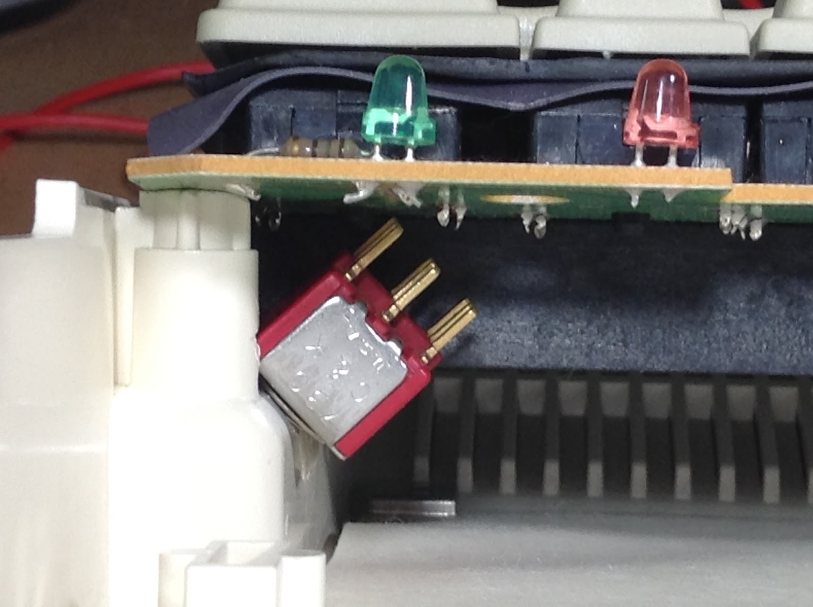
  1. That's where the 65C02 is
  2. It's the only place with any space. See the photo below (um...yes, I need to clean the keyboard).
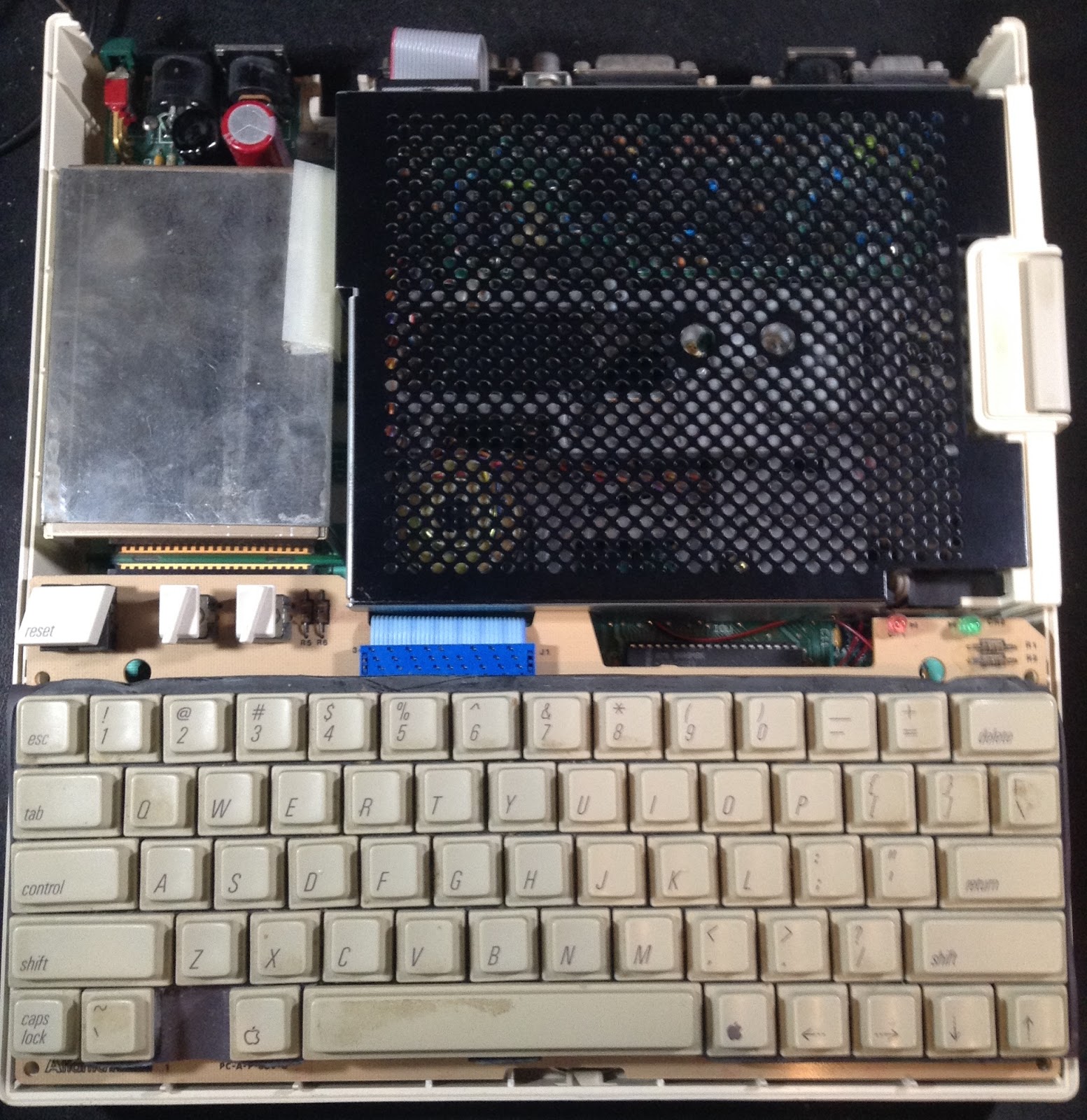
  • The keyboard has a short ribbon cable connecting it to the motherboard. Move the keyboard straight away from the disk drive only enough for it to be clear of the drive. Rotate the spacebar end of the keyboard up. Disconnect the keyboard's ribbon cable from the motherboard and set the keyboard aside.
  • It's probably okay to leave any expansion card plugged in
  • Remove the screws from the power supply. Slide the power supply just a bit towards the power switch to unplug it. Lift up and set aside.
  • Unplug the floppy drive cable at the motherboard
  • Turn the //c upside down again
  • Remove the screws holding the floppy drive
  • Lift the motherboard up. The floppy drive should be laying on the work surface underneath. There may be metal donuts on the drive or still on the posts on the bottom of the case. Move the drive and donuts aside.
  • Turn the //c right side up again
  • Remove all of the screws around the edge of the motherboard
  • Remove the motherboard and set aside
Mounting the switch

A reasonable (least bad) place to mount the switch on the case primarily depends on whether or not a //c carry case is being used. The //c has minimal protrusions. From the photo above, the most obvious places would be between the floppy drive and the back, or perhaps between the keyboard and the floppy drive. Neither of these works in a //c carry case.

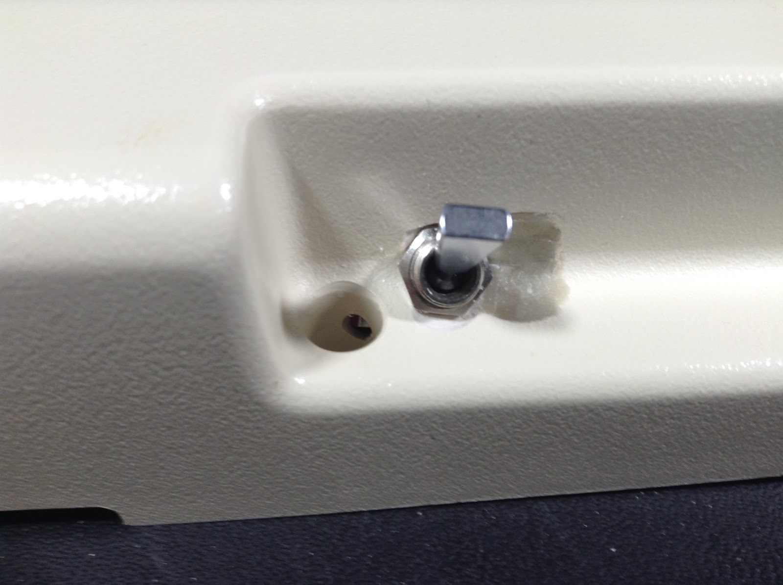
Having a //c carry case, I stole an idea from the volume control knob: the area under the side of the keyboard. The left side with the volume knob and headphone jack is already crowded so I drilled a hole on the right side.

The hope is that in normal mode, the switch won't protrude. When the internal drive is disabled it would be okay to stick out.

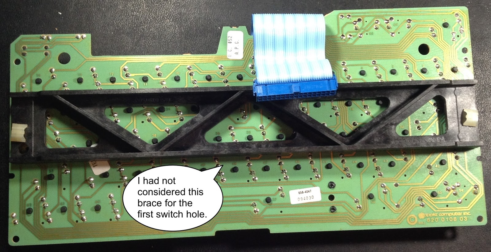
The older //cs have a keyboard brace. The switch hit the brace.


I searched a bit for smaller 3PDT switches and they seemed to be about the same size as the one I already had.

Early //c expansion instructions say to remove the keyboard brace. For a majority of people, this is the best option. Having broken the arm of a Return key on a //e, I figured I needed to keep the brace.

The left side of the //c motherboard has RAM so since I was going to make another hole I raised it up to the corner where the case widens out.

Moving the switch closer to the drive also meant the switch hitting the post for one of the screws holding the top and bottom of the case together.


The test fit...wasn't acceptable.


This resulted in drilling a hole in the support. It was a bit low.
The result was tolerable.
Looking into that screw hole isn't pretty.


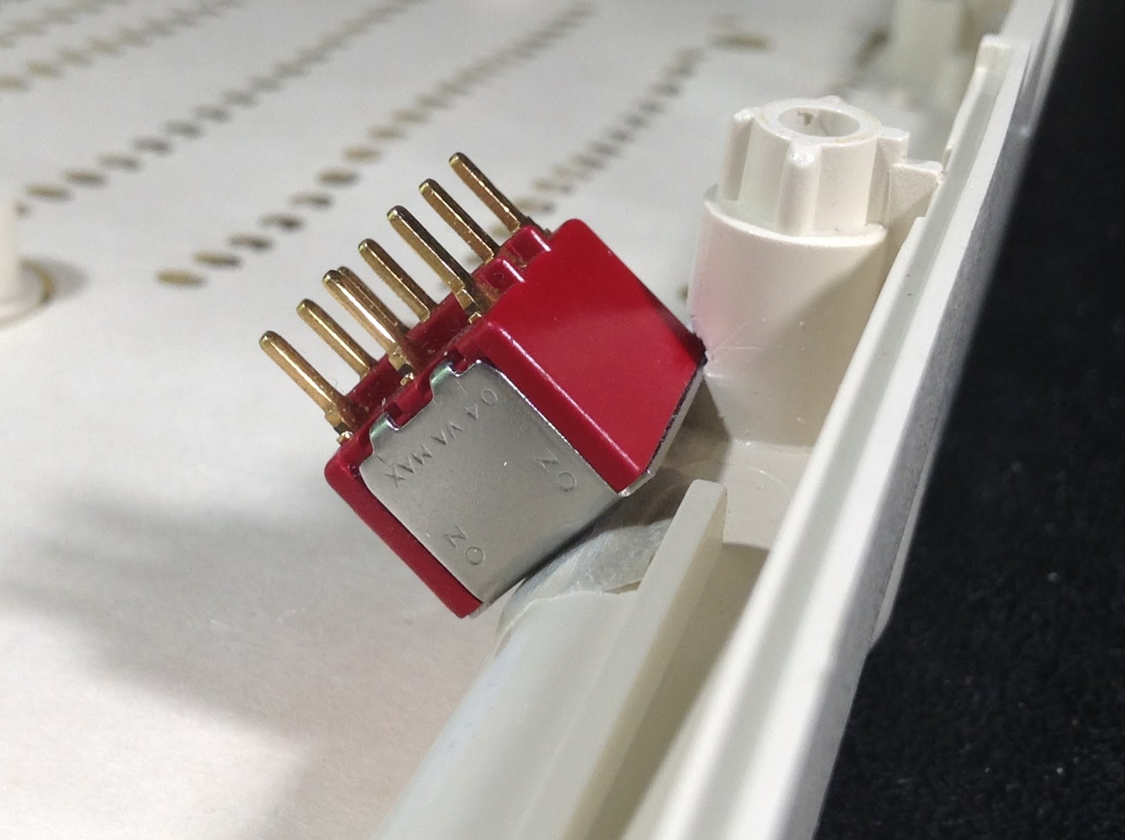
Caveat about pinouts

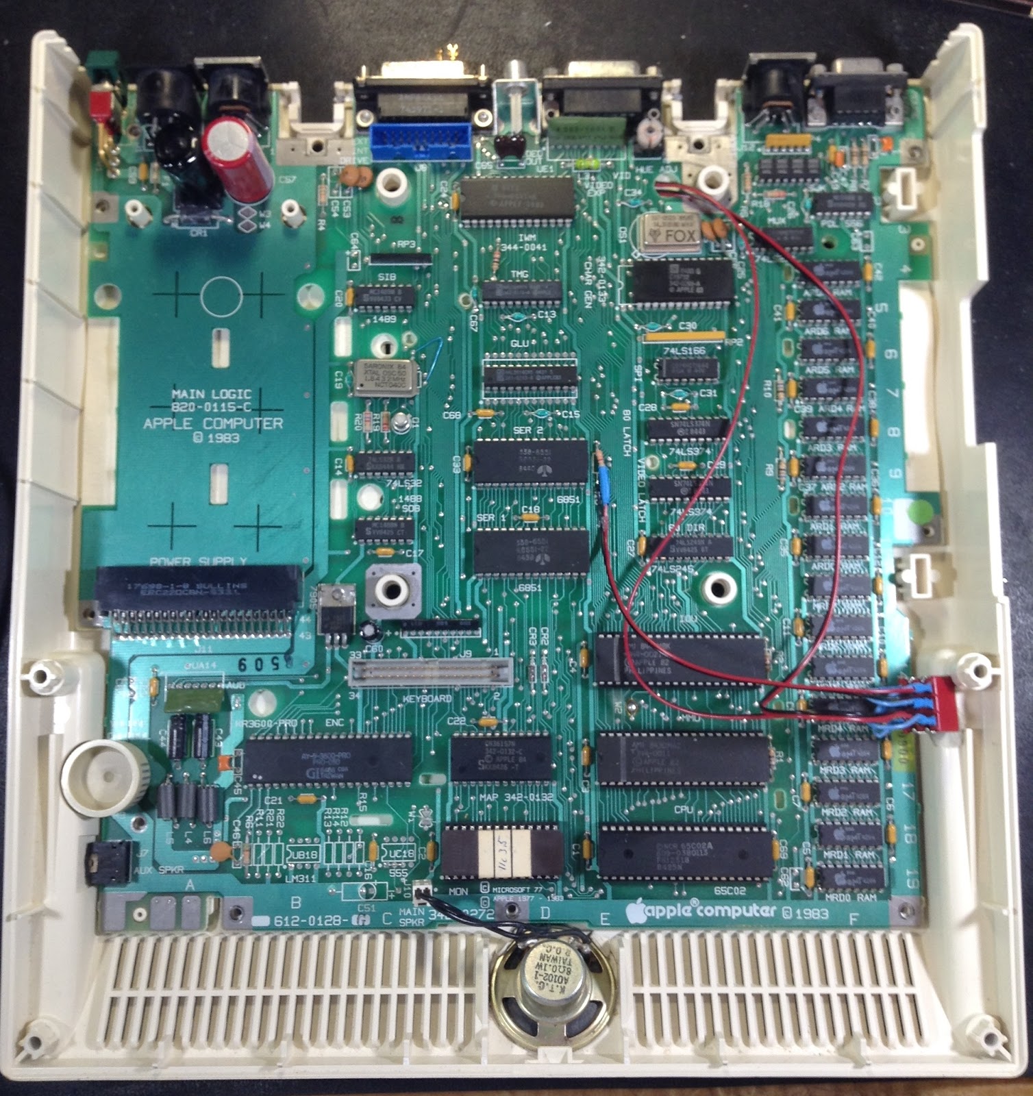
This document refers to a DB-19 connector, two pin headers (internal drive) and dual inline parallel (IWM controller). Each numbers pins in different ways. Even better, much of the work is on the bottom of the motherboard so is inverse!

Connections used

DB-19 #9 - external interrupt/drive 2 enable via one leg of R16
DB-19 #17 - drive 1 enable

Header 14 - internal drive enable

IWM 20 - drive 1 enable
IWM 19 - drive 2 enable

R16 is the pull up resistor used with DB-19 #9. The leg connected to DB-19 #9 should be desoldered and wires run to the through hole and the leg. On my motherboard the leg is closest to SER 1.

Switch wiring

I used three sets of two conductor wire. The sets are:
  • IWM 19 & 20
  • Drive enable 1: Internal header 14 & DB-19 #17
  • R16 through hole (DB-19 #9) & resistor to 5V
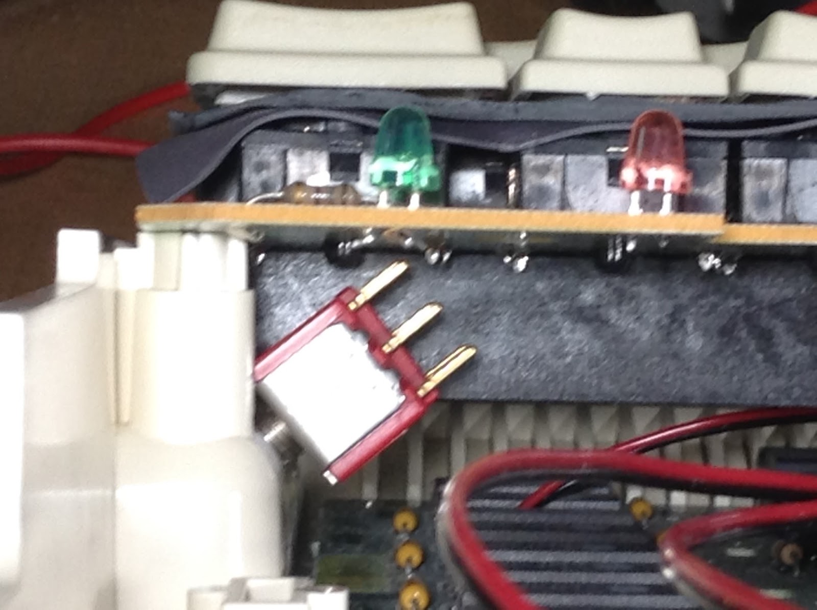
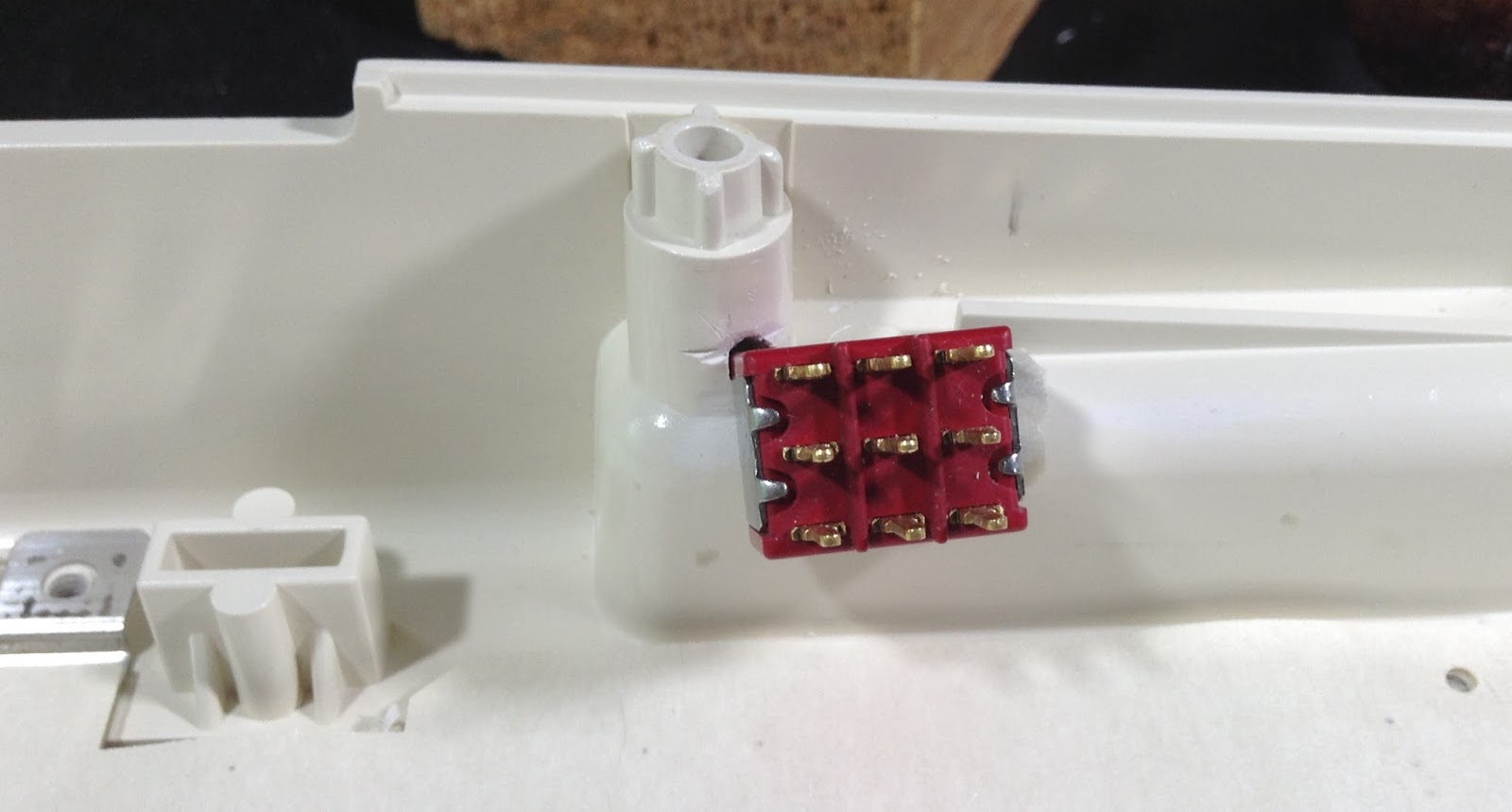
In the following table, each enabled connector need a jumper to the corresponding disabled connector. The colors are for the wiring in the photos.

Internal drive enabled IWM 20 red IWM 19 black R16 +5V red
Outgoing signals Internal drive 14 red DB-19 #17 black R16 to DB-19 #9 black
Internal drive disabled R16 +5V IWM 20 IWM 19

I used heat shrink on the enabled and disabled connectors mainly due to the length of the connectors.

Motherboard mods

The least painful way I could figure out how to do this mod was to cut the drive enable traces on the motherboard. The drive 1 enable lines for the internal drive and DB-19 are cut.
  • DB-19 #17
  • Header 14
These can be confirmed by checking connections to IWM 20 & 19. On my motherboard, the traces were easiest to cut on the back and were easy to find.

Here IWM 20 (drive 1 enable) has a trace to the internal drive and DB-19 #17 (external drive 1 enable) has a trace.


For each trace cut, two wires were run. Do not run wires through the holes for the drive posts. Clearly I need to figure out the runs before soldering.

Since the wires are on the bottom of the board, they have adhesive in a couple of places.


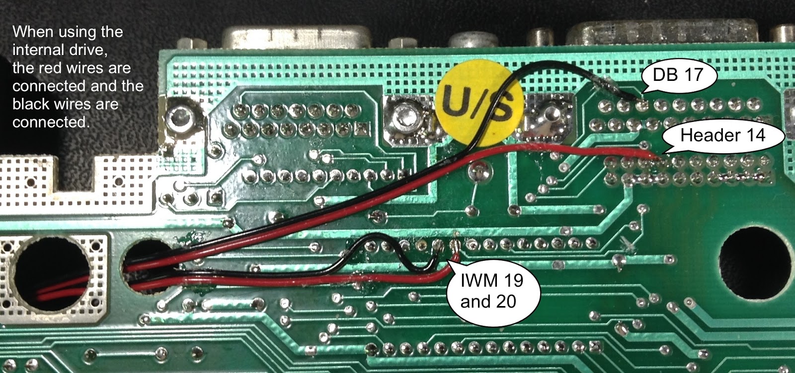
R16 is the pull up resistor used for the eternal drive interrupt, DB-19 #9. One of its legs connects to DB-19 #9, the other to 5V and SER 1. Use a continuity tester to determine the leg that runs to DB-19 #9 and desolder it. Run wires to the through hole and another to the resistor leg; heat shrink is a good idea for covering the connection to the resistor leg.

Since I didn't trim the switch contacts, I bent them. The blue wires are the jumpers between the top and bottom contacts.


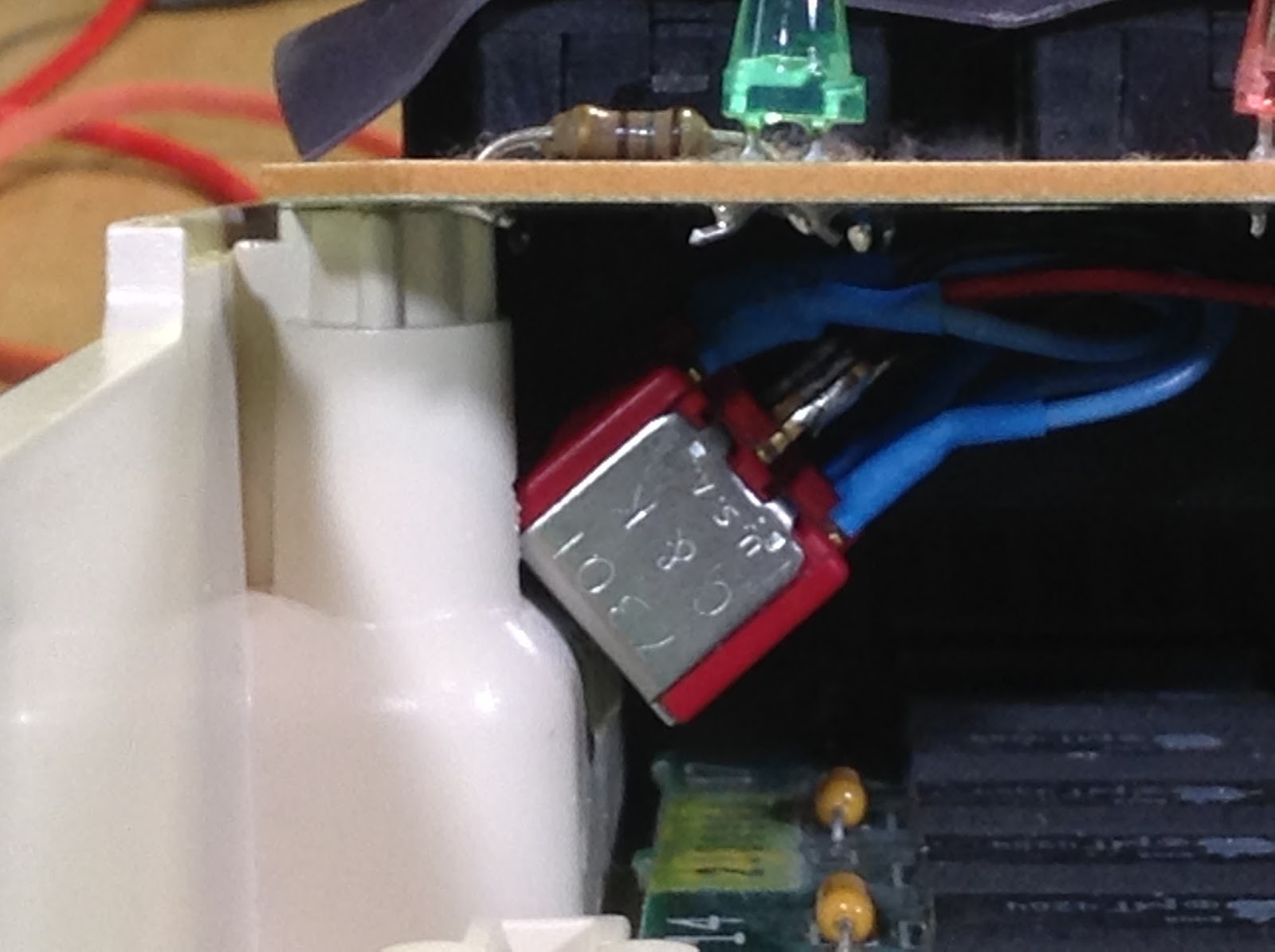
I forgot to shoot closeup of R16. Hopefully the entire board view will suffice.


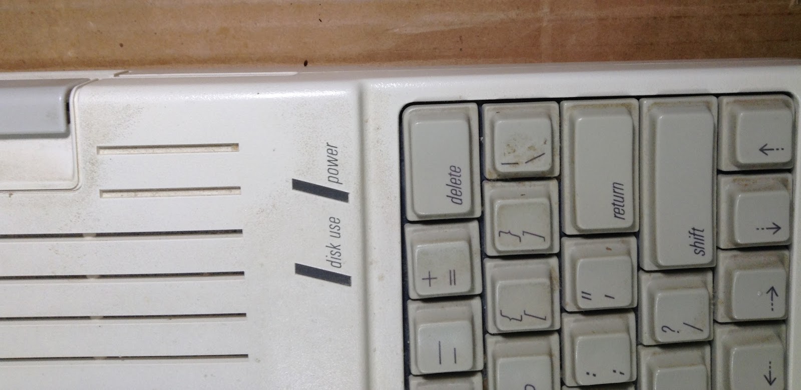
This is normal node, internal drive enabled. (Yes, I know the keyboard needs a cleaning.)


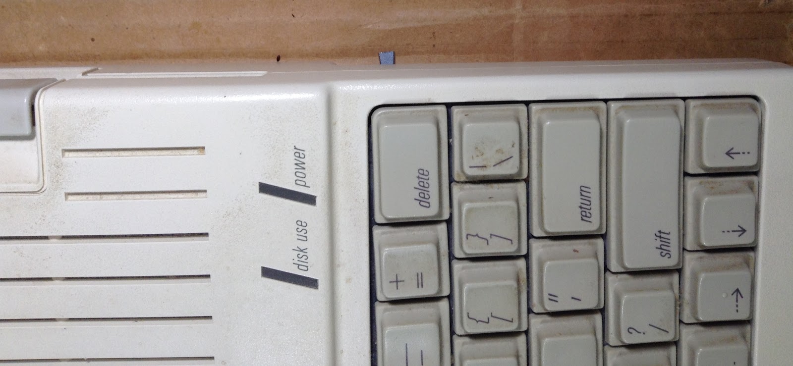
Here the internal drive is disabled. (Look beneath the Delete key.)


How about changing the internal drive to Drive 2 and booting an emulator as Drive 1?

This actually works for 5.25 drives and is easier to wire - and it breaks SmartPort. A workaround is to cheat: disable the internal drive, boot an emulator and then enable the internal drive. (The emulator becomes Drive 2.)

The 5.25 drive number swap is different in that:
  • A double pole double throw (DPDT) switch is needed instead of a 3PDT
  • No need to do anything with R16
Traces still need to be cut and jumper wires soldered on.

Saturday, July 30, 2016

Boot block for PRODOS or PRODOS1

Note: This project has been superseded by John Brooks' ProDOS 2.4 at http://www.callapple.org/uncategorized/announcing-prodos-2-4-for-all-apple-ii-computers/

My previous project - the huge PRODOS that contains both PRODOS 1.9 and 2.0.3, to boot the latest ProDOS 8 for any Apple II - was a bit hasty.

Certainly nobody wants a longer boot time, though this was not a big problem to me. (We pay for convenience.)

Having created a mutant PRODOS is confusing. There's no way to know what's in it without booting twice, or finding the file sizes in the file. This is annoying but not horrible.

What pushed me in another direction was the extra wear and tear on vintage hardware.

I had also broken an old server adage: Thou shall not perform unnecessary I/O.

The result was a boot block for PRODOS/PRODOS1 which will boot PRODOS on a //e compatible with a 65C02, otherwise it boots PRODOS1. If '1' was pressed, PRODOS1 is selected.

A boot block by itself is not at all user friendly, so a Boot Block Utility was cobbled together. Boot Block Utility contains 3 boot blocks:
  • common PRODOS,
  • GS/OS era, and
  • PRODOS/PRODOS1
Existing boot blocks can be read and will be compared against the 3 loaded boot blocks. Any of the boot blocks can be written to disk.

bootblockutil.dsk has PRODOS/PRODOS1 as its boot block, but the utility is primarily BASIC displaying lowercase so doesn't actually run on an Apple ][+.

Sorry about the Release being set to 2. Read on for the saga.


Warning: 6502 microprocessor knowledge is useful for the rest of this piece.

The purpose of the ProDOS boot block is to find a file called PRODOS in the volume (root) directory of a disk, load it, then JMP to it. A block is 512 bytes.

My first thought was to write a little PRODOS that turned around and loaded PRODOS1 or PRODOS2. To do this would require what I had been putting off: dissembling the PRODOS boot block then copying a bunch of it.

Eventually I settled on da65 in http://cc65.github.io/cc65/ for the disassembler. I use the https://sourceforge.net/projects/dev65/ cross assembler. (da65 does not produce entirely Dev65 friendly source.)

Walking through the disassembly started me wondering how many corners I could cut with my boot director. Remembering to avoid unnecessary I/O, it looked like I could use the volume directory that the boot loader had already read.

For those unfamiliar with Apple II 5.25 inch floppy I/O, it is quite low level. There is direct control of the read/write head movement. The data from the drive is 6 data bits per byte which must be read every 32 cycles. (Most 6502 instructions take from 2 to 7 cycles.) The boot ROM reads the 256 byte sector at track 0, sector 0 and executes it. ProDOS uses 512 byte blocks. So the PRODOS boot loader needs a) to read another sector for rest of the boot block and b) needs it's own 5.25 disk routine to read the PRODOS file from the disk. (Later disk devices are expected to have ROM based drivers to do the I/O.)

Uh, so mucking around with the 5.25 code was something I really truly wanted to avoid.

After looking at the boot code it seemed possible to make changes to it instead of writing a separate boot director.

This would also require two copies of ProDOS. I'm assuming that the number of II+ and unenhanced //e users is a minority of the Apple II user base, so PRODOS should be ProDOS 2 and PRODOS1 would be for the older machines.

Over 20 bytes would be needed to check for ProDOS 2 requirements (//e compatibility and a 65C02) and act accordingly. Checking for '1' being pressed to select PRODOS1 would take another 12 bytes.

Most of the code in the boot block is fairly tight but there are a few easy areas of opportunity.

The first looks like an odd signature at the beginning.

L0800:  .byte   1       ; indicates a boot block/sector
        sec
        bcs     L0807   ; branch always taken
        jmp     LA132   ; someplace in RAM
       
L0807:
 

There is some orphaned code, likely for the Apple /// from which ProDOS borrows heavily from. (da65 didn't give it any labels, so it didn't find any references to it in the block.)

        lda     #$9F
        pha
        lda     #$FF
        pha             ; an RTS would branch to $A000
        lda     #$01
        ldx     #$00
        jmp     LF479   ; somewhere in BASIC?!


Then there is the end of the boot block itself...which contains the beginning of the 5.25 disk reader.

L09F2:  lda     $C08C,x
        bpl     L09F2
        brk
        brk
        brk
        brk
        brk
        brk
        brk
        brk
        brk


If booting from a 5.25, the BRK instructions are overwritten by the boot loader with a copy some of the disk ROM.

Shortening the "*** UNABLE TO LOAD PRODOS ***" message would also be easy pickings.

5.25 disk code is notoriously timing sensitive. Fortunately shifting the code down the eliminate the BRK instructions in the boot block was not a problem. 


The testing of the PRODOS/PRODOS1 boot block went well. (Code details follow.)

It then struck me that I would need to provide something that I haven't heard of before: boot block maintenance. Figured that I should be able to squeak by with BASIC and a bit of assembler in page 3.

PRODOS/PRODOS1 boot block Release 1 and Boot Block Utility Release 1 were put together. (They have separate release numbers because I've been around long enough to appreciate that these things have lives of their own.) Feeling confident, I created an SVN tag.

Shortly afterwards I found a bug in Boot Block Utility - an improperly quoted string. There was a "Save boot block to file" and not a "Load boot block from file", so I fixed that too.

The PRODOS boot blocks I looked at included the one on a disk with PRODOS 1.0 and another formatted with Apple's System Utilities. No change.

On a lark, I checked the boot block of a GS/OS 6.0.1 disk that was handy. Of course GS/OS 6.0.1 had a different boot block.

The major difference between the older PRODOS boot block and the GS/OS era boot block is support for "sparse" files. Some versions of ProDOS may skip writing a block that contains all binary zeros and indicate that this by the data block number being zero. (Block zero, the boot block, is always reserved for boot code so can never be used for data.) Binary zeros must be written to memory when the file loaded. This takes some bytes of code...well, at least the NOPs?! can go.

        ldx     #$01
        lda     #$00
        tay
L0900:  sta     ($60),y
        iny
        bne     L0900
        inc     $61
        nop     ; is this padding?!
        nop     ; at least it's not in the inner loop
        dex
        bpl     L0900


The address in the JMP of the odd signature had changed. So apparently it really is a signature, or maybe a checksum.

L0800:  .byte   1
        sec
        bcs     L0807
        jmp     L091C   ; someplace in the boot block

L0807:


Interrupts are disabled after the signature and are enabled before JMPing to the loaded code. (I decided to leave interrupts disabled.)

The orphaned code was also removed.

The failure message had its asterisks removed leaving "UNABLE TO LOAD PRODOS".

The 5.25 code was in the same place so those BRK instructions at the end of the block could go. Actually the load and branch instructions were replaced by BRKs. The GS/OS boot block copies more of the disk ROM than its predecessor. So 5 more bytes that can get moved out of the boot block.

L09F2:  brk
        brk
        brk
        brk
        brk
        brk
        brk
        brk
        brk
        brk
        brk
        brk
        brk
        brk


The "structured assembly" features of https://sourceforge.net/projects/dev65/ made me chuckle a bit at first, but I have really come to like it. Structured assembly is about removing annoying branch labels, allowing indentation for clarity. The added functionality for the boot block is:

                lda     kbd
                cmp     #'1'+$80
                if      eq
                 sta    kbdstrobe
                 beq    prodos1
                endif
                lda     rom_machid
                cmp     #06
                if      eq      ; //e compatible
                 lda    #$99
                 clc
                 sed
                 adc    #1
                 cld
                 if     pl      ; 65C02
                  dec   stoname
                  dec   unable_len
                 endif
                endif
prodos1:


The data is setup to normally boot PRODOS1.

Crunching the code enough for the changes was a bit of work. Saving bytes resulted in a complete clash of coding styles.

                if      eq
unable:          jsr    home
                 ldy    #$15
unable_len:      .equ   $-1
                 repeat
                  lda   unablemsg,y ; "UNABLE TO LOAD PRODOS1"
                  sta   $05B1,y
                  dey
                 until  mi
                 repeat
                 until  pl     ; infinite loop

readinc:                       ; ugly place to insert a subroutine
                 jsr    L0927  ; read block
                 bcs    unable ; < 128 bytes away
                 inc    $61    ; high byte address of block to read
                 inc    $61
                 rts
                endif


Sadly I did not find enough bytes to calculate the number of data blocks correctly. A file whose size is a multiple of 512 may have an additional block read or the following block in memory zeroed.

Having 4 bytes free, a check was added for the file size. Due to a possible off by one for the number of blocks, the PRODOS/PRODOS1 boot block restricts the size of the file to 39.5K. (Mostly. The number of blocks is calculated by shifting the second byte of the size; there weren't enough bytes to check the third byte of the size. Theoretically a file between 64K and 103.5K will be partially loaded.)

The boot code reads all 4 directory volume blocks. I didn't think there are enough bytes left to do reads when necessary.

There are still a bytes that can be freed up but I skeptical that there are enough to do anything useful.

The result is Boot Block Utility Release 2 which includes PRODOS/PRODOS1 boot block Release 2.

The PRODOS/PRODOS1 boot block source.
The assembler listing.

Saturday, July 9, 2016

Booting the right ProDOS 8 for any Apple II

Note: this has been superseded by Boot block for PRODOS or PRODOS1

Apple II ProDOS 8 version 2 requires:
  • At least 64K of RAM,
  • A //e compatible machine, and
  • A 65C02 microprocessor.
(The original) Apple ][ and Apple ][+ users must use ProDOS 1.x.

So continuing the time honored technology tradition of creating solutions in search of a problem,  I created a front end to start one of the two copies of ProDOS in the PRODOS system file.

When a //e compatible (which includes the //c and IIgs) with a 65C02 is found, ProDOS 2 is started. Otherwise ProDOS 1 is started.

Pressing '1' or '2' during the considerably longer boot time forces the start of the selected ProDOS.

A CiderPress friendly copy is at PRODOS#ff0000 which is over 33K (67 blocks) and contains ProDOS 1.9 and 2.0.3.

A zipped 140K disk image is at prodos1and2.po.zip and contains:
  • The aforementioned PRODOS (1.9 and 2.0.3)
  • BASIC.SYSTEM
  • PRODOS1AND2.BIN - the front end
  • PRODOS1AND2.HLP - BASIC program with the help text for PRODOS1AND2
  • PRODOS1AND2 - ugly little BASIC program to create your own PRODOS from two other copies of PRODOS
    • Warning: Two copies of ProDOS 2 probably won't work; there isn't enough RAM.
Note that PRODOS1AND2 and PRODOS1AND2.HLP display upper and lower case.

Thanks to Andrew Jacobs for his Dev65 cross assembler.

This is intended for those wanting to create Apple ][+ friendly ProDOS disks.